After holidays and many other distractions, I am finally able to get back to work on my Raspberry Pi interface.
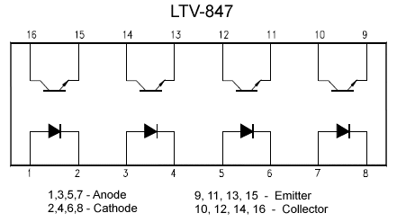
Here is the GPIO input circuit that I came up with using an opto-coupler for protection. The opto-coupler that I chose is the LTV-847 (Jameco part number 878286) which provides 4 opto-couplers in a 16-pin DIP format.
Power applied to the anode and cathode will cause the internal LED to emit light. This is detected by the internal photocell which controls the output. Because there is no electrical connection between the input and output sides, opto-couplers are handy for connecting between very different voltage levels. They are also excellent at preventing the introduction of electrical noise into a system. For this application, the isolation will provide electrical protection to the Raspberry Pi.
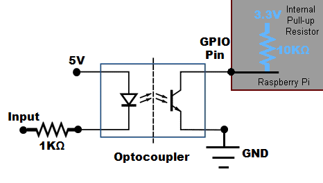
The complete circuit for using this is shown below. The 1KΩ resistor on the input is for limiting the current that can flow through the LED. The 10KΩ pull-up resistor is internal to the Raspberry Pi. Be sure to set the pull-up option when you set the pin to input mode. Using a separate 5V power supply for the interface provides greater protection than powering this all from the 5V line on the GPIO header. If that line gets shorted to ground, or even if it just draws too much current, it can cause the Pi to suddenly reboot.
When the input is open, no current will flow through the detector and the Raspberry Pi will see the pin hi due to the pull-up resistor. When the the input is connected to ground, current will flow and the Pi will see the the pin as low, since it is effectively connected to ground now.

